
Raspberry Pi 0 W + sensors + OLED display = temperature monitoring and calendar
2022-10-05 (updated )
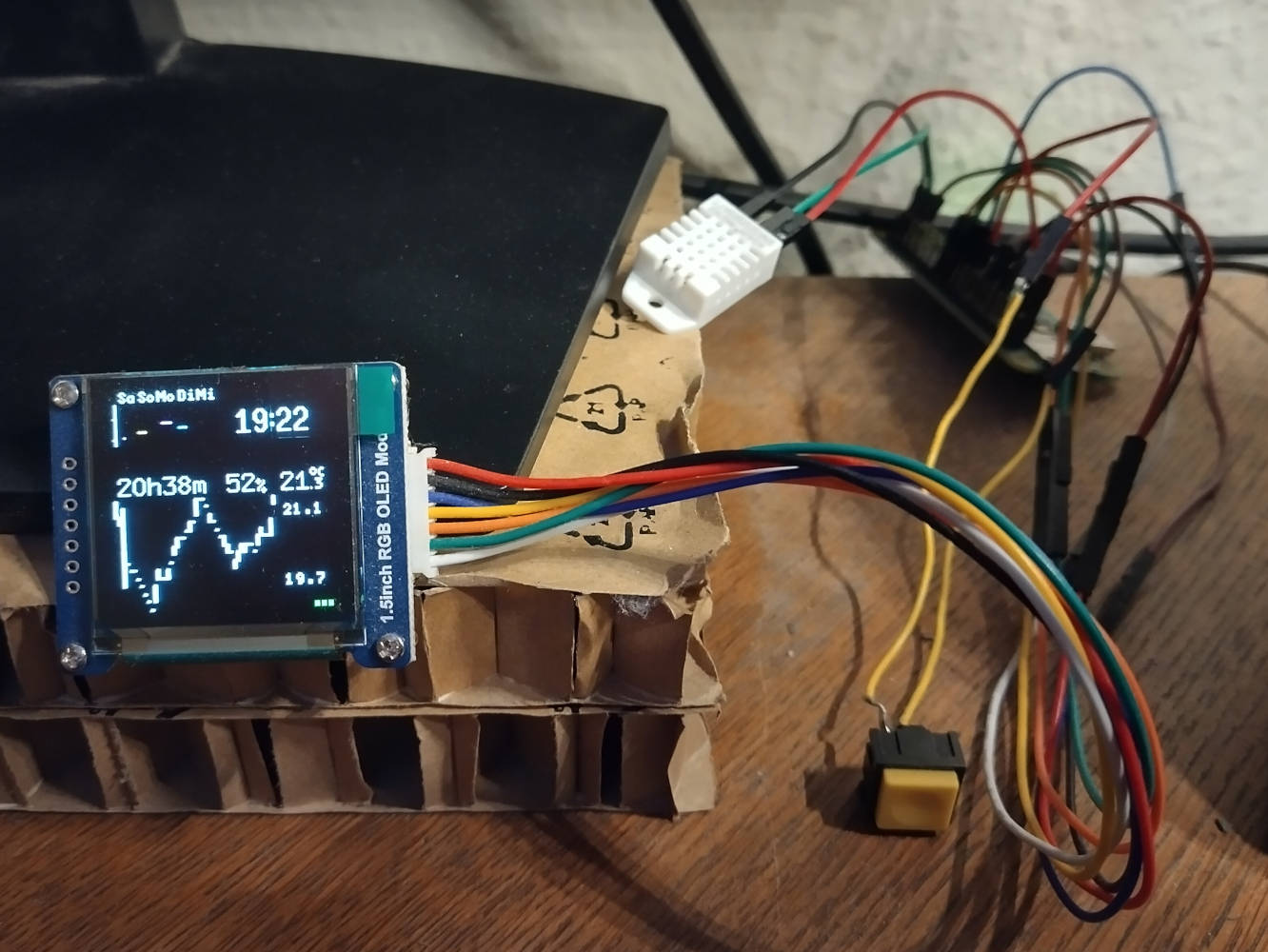
With this project, I monitor the temperature and humidity in my room. Measurements are taken every 10 minutes and saved in an SQLite database. Additionally, the display shows the upcoming appointments of the next five days: each of the 24 rows represents one hour and each pixel in a row represents 5 minutes. In the middle, the time until the next appointment, the relative humidity and the current temperature are shown. Below that, a graph shows the temperature of the last two days. When activating another display mode (not active in the picture), this area of the display instead shows the next seven appointments.
Hardware
- computer: Raspberry Pi 0 W
- temperature and humidity sensor: AM2302 (wired DHT22)
- OLED display: 1.5 inch SSD1351 (Waveshare)
- yellow push switch: TRU Components PBS-18B 701912
The components are connected to the Pi as indicated in the wiring diagram below (made using Circuit Diagram).
Wiring of the SSD1351 to the Pi (pinout):
- VCC ↦ 3.3V
- GND ↦ GND
- DIN ↦ SPI0 MOSI (GPIO 10)
- CLK ↦ SPI0 SCLK (GPIO 11)
- CS ↦ SPI0 CE0 (GPIO 8)
- DC ↦ GPIO 25
- RST ↦ GPIO 27
Wiring of the AM2302 to the RPi:
- VCC ↦ 5V
- second pin ↦ GPIO 26
- third pin ↦ (unused)
- GND ↦ GND
Wiring of the push switch to the Pi: one pin to GPIO 19, the other to 3.3V.
Software
The Raspberry Pi 0 W is running Raspberry Pi OS 11 (bullseye). It is advisable to enable SSH and configure a WLAN network before booting the RPi for the first time. As explained in many tutorials online, this boils down to modifying the SD card image. Create an empty file /boot/ssh to enable the SSH daemon, and configure the credentials of your WLAN network in /etc/wpa_supplicant/wpa_supplicant.conf. This blog post describes how to set up the initial user and password. Make sure to set dtparam=spi=on in your /boot/config.txt, otherwise the SPI connection to the OLED display will not work.
All of the following software is written in Rust and available on GitHub. take_measurements requests the current temperature and humidity from the sensor. To mitigate transmission errors, the median of five readings is used. The final reading is saved in the specified SQLite database (mine is named sensors.db) along with the current time. refresh_json downloads the latest calendar entries from my Trilium Notes installation and saves them in a JSON file (events.json). status_check gathers some miscellaneus status information on my other computer systems. The provided example just checks whether GitHub and GitLab are up. display_all processes all of this data and displays it on the OLED. It is run by another Python script (turn_on.py) whenever the push switch is pressed.
Below is the crontab of the pi user. status_check is run every five minutes. take_measurement is run every ten minutes. Fifteen minutes into the hour, any new calendar entries are synced using refresh_json. To avoid OLED burn-in, the display is turned off every minute (if it was on previously).
*/5 * * * * /home/pi/status_check /home/pi/sensors.db 2>/dev/null >/dev/null
*/10 * * * * /home/pi/take_measurement /home/pi/sensors.db
15 * * * * /home/pi/refresh_json --no-weekly
* * * * * /home/pi/display_off off
For performance reasons (and because the Pi doesn't have enough RAM), I cross-compile these programs using Nix. I'm certain there's a better way to do it, but the following method works for my purposes: in my NUR packages, run the following command to cross-compile all binaries: NIXPKGS_ALLOW_BROKEN=1 nix-build -A raspi-oled-cross. (Btw, this will first compile LLVM and rustc for some reason. There must be a way to avoid that...) As always, ./result is a symlink to the build artifacts. The binaries (and the libraries they depend on) may be copied to the Pi like this:
mkdir /tmp/nixstore
nix copy --extra-experimental-features nix-command flakes --no-check-sigs --to /tmp/nixstore $(readlink -f result)
rsync -r --links --info=progress /tmp/nixstore/nix pi@himbeere-null:~/
On the RPi itself, the binary needs to be adapted to Raspbian and placed in the proper position:
patchelf --set-interpreter /lib/ld-musl-armhf.so.1 nix/store/*-raspi-oled-*/bin/display_all
sudo mv nix /
Enclosure
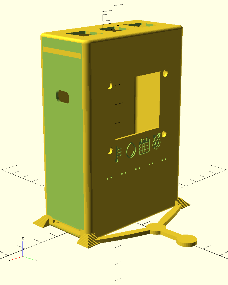
To make the whole setup look a bit nicer, I designed a casing using OpenSCAD. The image on the right shows the final result as rendered by OpenSCAD (.scad).
Raspberry Pi 0 W - Slim Case (by OhSnap) proved to be a great base to build on. I added some supports around it to ensure it won't topple over as easily. Since I was too lazy to measure the dimensions of my OLED display, I extracted the relevant part of Zoid, the Trapezoidal Under Cabinet 1.5" OLED Display (by rhattie). Feeling a little bit fancy, I decided to add some inset icons underneath. The pin holes will be useful to add some status LEDs later. Because one button will soon not be enough control, I added three button holders on the top. A library near me offers a 3D printing service so it was easy to get the case printed.
The new buttons and LEDs will need to be wired up to some unused GPIO pins. All LEDs are connected using a single resistor since these will only turn on rarely and even more rarely at the same time.
To make full use of the three buttons, I came up with a simple one/two-step selection menu to get to the most important functionality.
- Show time table and large clock
- (unused)
- Show temperature chart
- Show upcoming events
- Dismiss active action
- Show TOTP codes
- Next page
- (unused)
- Show RPi screensaver
This post will be updated soon™ to show to the final 3D print (which required some adjustments not yet mentioned).


